|
|
|
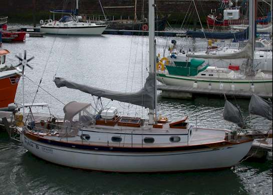
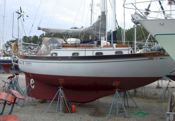
Lydia B Baba 30 cutter History & Technical summary
|
|
|
|
NB: The following notes were compiled for the purposes of the European Recreational Craft Directive (RCD) for boats entering the European Union. General The Baba 30 is a heavy displacement, full-keeled, double-ended cutter designed by Robert H. Perry of Seattle, Washington, USA for long-distance, bluewater voyaging. Some 230 Baba 30-s were built between 1977 and 1985 by the Ta Shing Yacht Building Company, Tainan, Taiwan, to standards at or exceeding Lloyds. Lydia B, hull no. 61, was built in 1979. Perry (www.perryboat.com) is the designer of the Baba 30 (a few were sold in the UK as the Westwind), Baba 35 and 40; the Tayana, Tashiba, Valiant, Norseman, Cheoy Lee, Hans Christian and many others. Approximately 5,000 Perry-designed bluewater cruising boats are currently afloat. Baba 30’s have completed many ocean crossings and circumnavigations. Principal statistics: Length on deck: 29’9" Beam: 10’3" Draft: 4’10" Displacement: 12,500lbs Ballast: 5,000lbs Sail area: 504 sq.ft. D/L: 379 SA/D: 15.0 Stability range calculated by the Wolfson formula: 139.58
Designer’s plans (11 sheets):
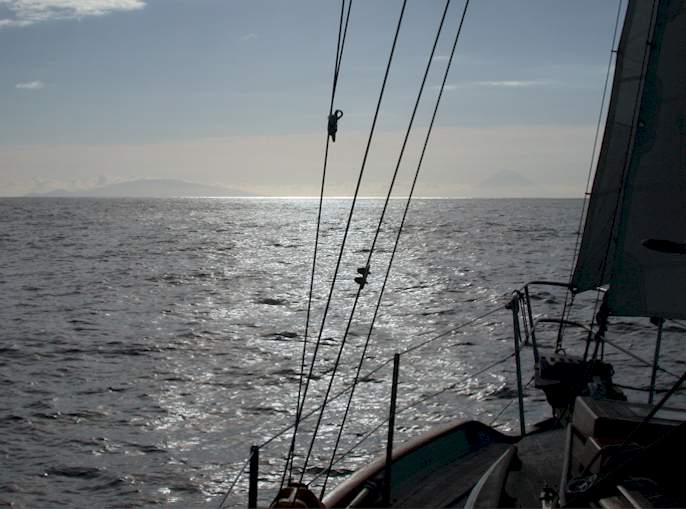
Lydia B history. Lydia B was built and fitted out by Ta Shing and first delivered to Juneau, Alaska, in 1979. Until 2001 she remained in the Pacific Northwest, principally in the Seattle, Washington area. Ian Laval bought the boat in British Columbia, Canada, in 1999 and took it to Victoria BC. She was registered in the UK in 1999 and has been a live-aboard boat for 12 years of her life, voyaging extensively in the Pacific Northwest, Caribbean and Atlantic. She has sailed the Inside Passage to the far north of British Columbia and completed three circumnavigations of Vancouver Island. Since 1999 to date (2004) Ian Laval has lived aboard and equipped the vessel for independent, long-distance passage-making. He chose the Baba 30 after another Atlantic passage in a different, 34-ft boat and has sailed Lydia B 18,000nm, including Pacific and transatlantic passages in a wide spectrum of conditions with no failure of boat or equipment. Lydia B has encountered many ocean gales, tropical thunderstorms and a Force 11 Atlantic storm (see attached log, relevant NOAA W/fax and account).
Principal passages 1999-2004. Jun 2000: Circumnavigation Vancouver Island, British Columbia, Canada (900nm) May/Jul 2001: Victoria BC via Inside Passage to northern British Columbia, Queen Charlotte Is, Victoria BC. (1,700nm) Sept 2001: Victoria BC to San Diego, S. California (1,550nm) Jan 2002: San Diego, California to Panama via Mexico, El Salvador, Nicaragua and Costa Rica (3,400nm) Apr 2002: Panama via Caribbean (San Andres & Isla Mujeres) to Washington DC, Chesapeake, east US (3,200nm) Jun 2003: Virginia US to Maryport, Cumbria, UK via Azores: 4,080nm) (Details of the above passages and recorded weather below are in Lydia B’s log).
Oct 2/01. N46 124W (off Oregon USA): gale. Gulf of Papagayo, Nicaragua, Mar 20-24 2002 – continuous Papagayo winds to 40kts. June 8-9 2002 N23.50 W083.11 (off W.Cuba) -- tropical storm. May 31-June 1 2003 N37.00 W67.30 (Atlantic) -- storm. Recorded wind 61kts, seas 30 to 45ft. (see NOAA surface analysis w/fax below). Jul 6 2003: N45.59 W16.13 (Atlantic) -- gale Account of Atlantic Force 11 storm encountered by Lydia B on May 31/June 1 2003 at N37.00 67.30W. Boston NMF Atlantic surface analysis weatherfax six hours post- storm-height transmitted on June 1, 2003. Lydia B’s position was approx. N37.00 69.00W, 550nm east of the Chesapeake, US, in the storm’s SE quadrant.
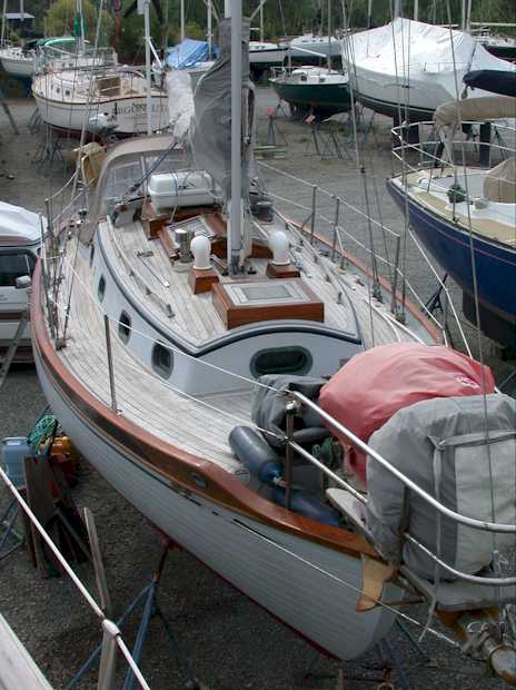
Lydia B’s position and the conditions can be verified by the Canadian mv Oleander and the Bermuda-registered ketch Wings of Time. VHF contact was logged with both vessels at 1900gmt on May 31 and 0800gmt on June 1 respectively. The storm developed with a rapid and unpredicted fall in pressure to 976mb and reached its height overnight at 0600GMT on June 1. Breaking seas can only be guessed at, but were probably between 35ft and 45ft, exacerbated by the boat’s position near the outer wall of a SSE-bound Gulf Stream current in opposition to the wind. Lydia B lay hove-to with storm jib and minimum reefed main and the wheel braked and lashed for four hours. The 2 crew remained below with companionway washboards in place. Breaking waves repeatedly crashed over the port side. The starboard portlights were regularly under solid water and the starboard deck was submerged for long periods. No water entered the boat and she did not feel stressed. All systems, including navigation lights, VHF and SSB radios, all electrical systems, engine, steering and rig remained fully functioning. At first light, past the storm’s height, all sail was removed and Lydia B ran under bare pole for several hours in very big following and breaking seas, steered continuously by the Monitor wind-vane at speeds routinely of eight knots. Although Lydia B carried a 4.57m parachute and 120m of heavy line it was not felt necessary to deploy it. It was considered wiser to escape the influence of the Gulf-stream current. The boat handled comfortably with major wind and seas astern on the starboard quarter and did not attempt to broach. Boarding cross-waves frequently filled the cockpit, knocking down the helmsman, and draining quickly. No damage to the boat, rig or systems was sustained. The cockpit lee-cloths were shredded by the force of the wind. Several items of spares were washed off the deck or floated out of the cockpit. Lydia B continued her passage uneventfully to Horta, Azores and thence to the UK. Storm logs transmitted ashore by HF radio e-mail June 1/2-03. -------------- Sole equipment failures on the 15,000nm passage from the NW Pacific to the UK were to a mainsail damaged in an accidental heavy weather gybe off Mexico and a worn seal on the Yanmar engine’s salt-water pump while moored in the Azores. The Panama Canal is a severe test of a small vessel’s mooring points during transit when large prop-washes are encountered from freighters in the locks. Many vessels have been severely damaged. Lydia B transited the Canal without incident. A feature of the Baba 30 is its small cockpit, designed to minimize potential problems caused by boarding seas. No sea-water has entered the interior of the boat in the current owner’s 18,000nm of open-ocean voyaging, except in the normal way into the bilge via the stuffing box
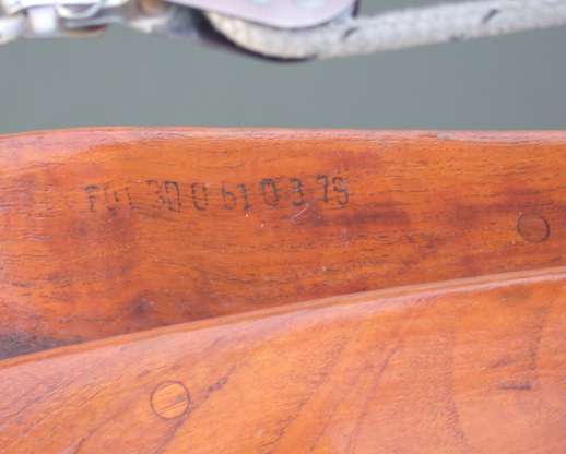
1. CE Category :D. NB: CE category D was chosen solely to meet the minimum legal requirements for entry to the European Union following her passage from the Pacific Northwest to the UK. Under the European Recreational Craft Directive (RCD) the placing of a vessel in any particular category in no way restricts the vessel to any inshore or offshore area. Lydia B may be sailed and sold in the EU on the same basis as any other vessel regardless of category. Please refer to the vessel's Pacific and Atlantic voyaging history, and the extensive history of sister boats including a circumnavigation and many ocean crossings, for evidence of its safe ocean-going capability. 2.1. Hull identification: FDI 30 061 0379 (stamped on starboard quarter cap-rail).FDI = Flying Dutchman International, the United States company who commissioned the boat for building by the Ta-Shing Yacht Building Company, Tainan, Taiwan. 30 = Baba 30. Hull number 061, March 1979.
2.2. Builder’s plate: Manufacturer : Ta Shing Yacht Building Company, Tainan, Taiwan. Responsible person : Ian Laval Design Category : D (But see note above) Maximum recommended load: 1700kg Maximum recommended number of persons: 5
2.3. Protection from falling overboard and means of re-boarding.
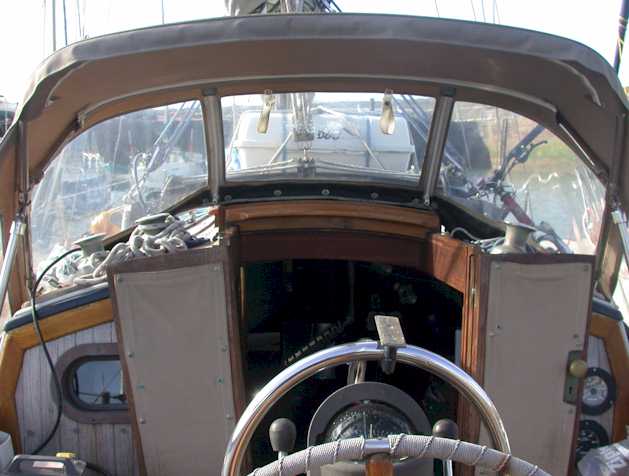
2.4. Visibility from the main steering position.
2.5. Owner’s manual. An owner’s manual accompanies the vessel.
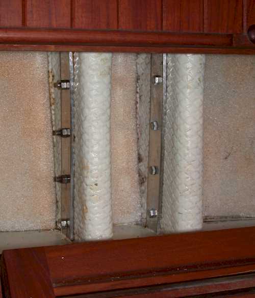
3.1. Structure. The hull is constructed of uncored, hand-laid fiberglass using alternating layers of 1.5oz mat and 24oz woven roving. There is a minimum of three pairs (one pair = one layer of 1.5oz mat and one layer of 24oz woven roving) in the topsides, four pairs in the bilge area and five pairs in the tuck and keel. The deck is constructed of three layers of 1.5oz mat alternating with two layers of 24oz woven roving and a core of 160mm marine ply. The deck is bonded to the hull with one layer of 1.5oz woven roving and one layer of 24oz woven roving. An 81mm x 27mm teak caprail is bolted through the deck and hull overlap with 6mm ss machine bolts counter-bored into the caprail at 216mm centres. The cabin top is constructed of three layers of 1.5oz mat alternating with two layers of 24oz woven roving with a core of 20mm end-grain balsa. There are seven 400mm x 400mm laminated teak deck-beams. Hull, deck and cabin-top are gel-coated. All bulkheads, shelves, berth-flats, counters and cabin sole are bonded to the hull with two layers of 24oz woven roving alternating with one layer of 1.5oz mat with a 130mm overlap. Where applicable, teak face veneer is removed under the bonding overlap. There are foam compression pads between bulkhead and hull. Structural strength is augmented by a solid teak keyhole bulkhead and 38mm bronze post at the after end of the saloon, a three-fifths teak bulkhead at the forward end of the saloon and a part-bulkhead at the after end of the forepeak. The hull is lined with teak battens for insulation. Iron ballast is 2268kg cast in one piece and encapsulated in chopped mat and resin dough. The mast is supported on a 650mm stainless steel post with 0.65mm wall. The compression post is partly encapsulated in a solid teak bulkhead above cabin sole level. The rudder blade is constructed of two layers of 1.5oz mat and two layers of 24oz woven roving filled with (12lb per cu ft) foam. The rudder stock is 38mm stainless steel with a 5mm stainless steel backbone plate. It is mounted in upper and lower delrin bearings mounted in a 70mm grp tube glassed to the hull. A 38mm stainless lower pintel is located in a press-fit cutlass bearing within a cast bronze heel faired and bolted to the hull. Engine beds are two layers of 1.5oz mat and two layers of 24oz woven roving over teak stringers. Chainplates are 6.5mm stainless steel with stainless steel deck plates. The chainplates are bolted to chainplate webs with 10mm stainless steel bolts with 3mm stainless steel backing plates. The webs are constructed of two pairs of 1.5oz mat and 240z woven roving on a core of 38mm marine ply. The webs are bonded to the hull with two pairs of 1.50z mat and 24oz woven roving. All the chainplates are accessible within the saloon.
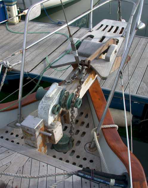
A 110mm x 110mm teak Samson post is bolted to the anchor-well bulkhead and the bowsprit and bonded to the anchor-deck and the hull. The 2.0m x 135mm bowsprit is constructed of laminated teak. The stainless steel bobstay fitting is let into the stem and bolted with three 10mm stainless steel bolts with backing plates. Whisker stay stainless steel chainplates are bolted to the hull with 8mm ss bolts with backing plates. A bowsprit eye-band (kranz iron) for forestay, bobstay and whisker stays is fabricated from 6.5mm stainless steel. Two 40mm x 100mm scuppers are built into the bulwarks on each side. A 127-ltr diesel tank fabricated from steel plate is housed in the bilge Two 160-ltr fresh-water tanks fabricated from stainless steel are secured under the port and starboard settees in the saloon. Both tanks are vented to the cabin-sides. Tanks, chainplates and structural metal are electrically bonded. Mast and boom are aluminium. One pair of spreaders. All stays 6.5mm 1x 19 stainless steel wire. (Headstay, forestay, backstay; one pair upper shrouds, one pair forward lower shrouds, one pair after lower shrouds, one pair after intermediate shrouds).
3.2. Stability and freeboard. Stability range calculated by the Wolfson formula: 139.58. Freeboard amidships with 70% maximum recommended load: 1.08m. NB: Refer to safe ocean voyaging history and heavy weather accounts above.
3.3. Buoyancy and flotation.
NB: Refer to heavy weather accounts above.
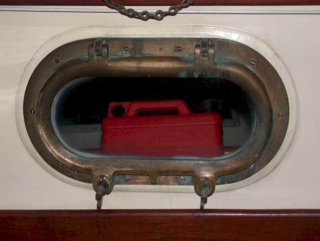
3.4. Openings in the hull, deck and superstructure. Openings are as follows: Forehatch, saloon hatch, companion-way doors and sliding hatch cover. Cockpit locker. 10 opening portlights. Rudder-stock plate for emergency tiller. Propellor shaft stuffing box. Galley mushroom vent. Two dorades and dorade-boxes. Anchor chain-pipe. 10 through-hull fittings. Engine exhaust outlet. Forehatch The opening is 510mm x 510mm with teak coaming 160mm deep on 40mm x 40mm laminated teak framing between the laminated deck beams 40mm x 40mm. The hatch cover is 22mm marine ply decked externally with teak and framed with 70mm x 35mm teak. A 250mm x 250 mm x 10mm thick perspex light is sealed into the hatch cover. The hatch cover is rebated and hinged to the after end of the fixed frame with take-apart stainless steel hinges (pins held by stainless cotter rings). Two bronze opening stays and one bronze locking clasp are provided. (Stays on forehatch and saloon hatch may be quickly removed for emergency exit). Saloon hatch.
The saloon hatch opening is 750mm x 750mm, with 160mm deep teak coaming on 40mm x 40mm laminated teak frames between 40mm x 40mm laminated teak deck beams. Two teak-framed opening lights are hinged to a 115mm x 115mm fore-and-aft teak framing piece and rebated to cover the hatch framing overall. A neoprene seal is fitted on each side of the hinge-line. Each light has one pair of bronze opening stays and one bronze locking clasp. Externally, each wing of the light is fitted with a grille of 8mm stainless steel safety bars. Glass is toughened, laminated and darkened for sunlight protection.
Companionway. The companionway opening is 670mm x 620mm (vertical plane). Companionway doors are solid teak in two wings on bronze hinges and with bronze lock and latch knob. A groove inboard of the doors accommodates solid teak washboards in four sections with rebated overlaps. Washboards can be dropped into place without removing the doors, which may be closed simultaneously. The sliding hatch is 800mm x 740mm, constructed of 22mm marine ply framed with solid teak and decked with teak. It is rebated over the hatch opening and slides on stainless steel beds. The hatch opens forward into a fixed teak and teak-decked housing. The sliding hatch is fitted with bronze sliding bolts to lock it in the closed position. Cockpit locker. The cockpit locker opening (port side of the cockpit) is 840mm x 370mm, formed in the grp deck moulding, with water dispersal channels at the rear and on both sides. The cockpit lid is 22mm marine ply framed and decked in teak. It is fitted with two stainless steel locking clasps and a full-length stainless steel piano hinge. Portlights. The cabin is fitted with ten 350mm x 170mm cast bronze opening portlights with external cast bronze retaining plate. Internal hinges are integrally-cast knuckle and bronze pin. Latch fastenings are 10mm bronze bolt and bronze wing nut. Lights are toughened, laminated glass. Seals are provided by 8mm sq neoprene cord.
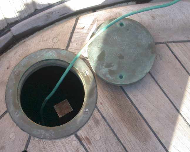
Rudder-stock deck plate. A 110mm opening is provided in the cockpit deck above the rudder-stock to fit an emergency tiller in case of wheel steering failure. A bronze deck-plate screws into a bronze housing. Stuffing box The conventional flax-filled bronze stuffing-box is accessible through the cockpit locker. Galley mushroom vent A bronze mushroom vent is fitted above the galley with access to handle to screw closed from inside the vessel. Dorade vents. Two swivelling 100mm cowls are fitted on teak dorade boxes with mesh filters on each side forward of the mast. Anchor chain-pipe A 75mm dia. Bronze anchor chain-pipe with bronze taper-fit cap is fitted in the anchor-deck. Engine exhaust outlet. The engine exhaust outlet is on the starboard quarter and is connected to the engine via an anti-siphon loop high in the stern below the cockpit deck. Through-hull fittings. There are ten through-hull fittings as follows: 1. Anchor-well drain 2. Head sink-waste 3. Holding tank exit 4. Sea-water to toilet 5. Knot-meter 6. Port and starboard cockpit drains (2) 7. Engine seat-water intake/galley seawater 8. Galley sink drain 9. Bilge exit All through-hull fittings are bronze with bronze taper-cone lever-action valves with the exception of the sea-water to head valve, which is a bronze valve with stainless steel ball. All skin fittings are 38mm unless otherwise described. Anchor-well drain. Valve located in forepeak forward on starboard side. Head sink-waste. Skin-fitting 32mm. Valve located in sink cabinet within head compartment. A non-return valve is fitted. Holding tank exit. Valve located in sink cabinet within head compartment. Sea-water to toilet. 32mm. Valve located in sink cabinet within head compartment. The toilet water inlet is fitted with an on-off valve. Knot-meter. Fitting located in sink cabinet within head compartment. Port-side cockpit drain (50mm) is piped to valve located under starboard quarter-berth. Starboard-side cockpit drain (50mm) is piped to valve located under cockpit locker. Engine and galley seat-water intake (combined) are located under the cockpit locker to port. Galley sinks drain via valve within sink cabinet to port. A non-return valve is fitted. The bilge pumps (electric and manual) drain to valve located under the cockpit locker to port.
3.5 Flooding. Cockpit. The cockpit is 2.05m long by 1.75m wide tapering to zero at the stern (canoe) end. The cockpit is within an integral raised coaming 180mm above deck height. The companionway sill is 105mm high. The cockpit well is 0.99m long x 0.6m average width x 0.45m deep. The floor of the cockpit is 385mm above the designed waterline. There are two 50mm drains with bronze strainers. The cockpit well is fitted with teak floor-grilles. NB: Refer to heavy weather accounts above. In the Atlantic storm described the cockpit was filled on numerous occasions and drained quickly. No sea-water entered the vessel.
The bilge is pumped out by
All other openings are described in 3.4 above.
3.6 Manufacturer’s recommended maximum load.
1,700kg
3.7. Liferaft stowage.
A liferaft canister cradle is fitted above the sliding hatch cover with firm anchorage points for liferaft canister tie-downs.
3.8 Escape Exit is practicable via the forehatch, main saloon hatch and companionway (described in 3.4).
3.9. Anchoring, mooring and towing. The vessel is fitted with a teak Samson post on the bow (described in 3.1).
A cleat is provided on the anchor windlass. 180mm stainless steel spring and stern cleats are through-bolted with stainless backing plates on each side of the boat, with appropriate closed fairleads. The vessel is fitted with a manual anchor-winch. Ground tackle carried on bronze bow-rollers is one 17kg CQR with 50m of 8mm high-tensile galvanized steel chain and 50m of 22mm three-strand nylon; and one 16kg Bruce anchor with 20m of 8mm galvanised steel chain and 60m of 22mm three-strand nylon. A Danforth anchor with 10m of 8mm galvanized steel chain and 35m of 22mm three-strand nylon is fitted at the stern for stern anchoring. An anchor pendant with chain hook is attached to the bobstay fitting at the waterline.
4. Handling characteristics The vessel is light on the helm and easy to balance. It requires extra headsail area in very light winds and is thoroughly at home in heavy weather. Problems going astern are those normally associated with a full keel. Speed under motor alone is 5.5kts at 2,400 revs. Overall average speed over last 15,000nm: 4.3 kts.
5.1. Engine and engine spaces.
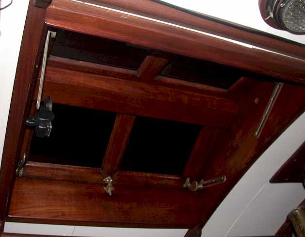
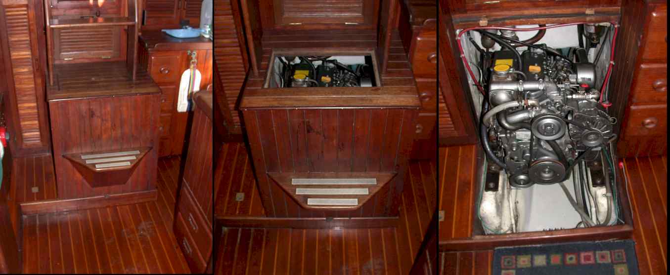
The diesel engine is a 21.33KW Yanmar 3GM30F fresh-water cooled unit. It was installed in 1997 and has run for 2,900 hours (June 2004). The manufacturer’s handbook and a full Yanmar workshop manual are provided. The engine is located under a removable teak hatch beneath the companionway. The hatch is fitted with two inspection panels – one above and one to the starboard side. The hatch may be lifted off for complete engine access. The hatch is lined with non-combustible material. The engine is on rubber mounts bolted to grp-covered teak stringers glassed to the hull. A white plastic pan is beneath. All essential service parts are accessible, including oil and fuel filters, dipstick and oil evacuation point, alternator, water-pumps and drive belts. Fuel hoses are fire-resistant. A 127-ltr diesel tank is described in 5.2 below.
5.2 Fuel system A 127-ltr diesel tank is located in the bilge immediately forward of the engine. The tank is fabricated in steel plate to fit the bilge space. The tank was removed for inspection in March 2004, pressure-cleaned internally, shot-blasted externally and re-epoxied. The tank contains one lateral baffle and has a 300mm x 200mm inspection plate with neoprene gasket. Provision is made in a recess at the forward end of the tank for 50mm filler pipe and a breather pipe, to plates above-deck on the port side amidships. A recess at the after end of the tank contains the fuel feed to the engine, the return from the injectors and a dipstick. The tank is secured in the bilge by two oak battens screwed to the floor framing. All hoses are fuel-rated. Fuel flows to a Racor pre-filter and thence through the engine fuel pump and filter on the starboard side of the engine. Cooling sea-water flows from a water-intake filter to the engine through a heat exchanger to a mixing elbow and silencer and exits via an anti-siphon loop high in the stern.
5.3 Electrical system (12v). Power-sources:
(Provision is also made for 240v & 110v shore-power). Power is stored in the following battery banks:
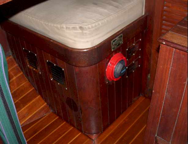
All batteries are housed in lidded nylon/plastic boxes fixed permanently below the quarter-berth astern of the navigation desk and adjacent to the switching panel. All the batteries are securely tied down. The compartment housing the batteries is vented by four stainless steel grilles.
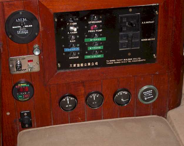
A 10-amp shore-power battery charger is fitted. Alternator output is controlled by a three-stage digital regulator. A 360-amp battery switch is wired into the electrical system. The system also includes an Echo-charge digital controller; this automatic charge-switching device priority-charges the starter battery then automatically switches the charge to the house bank without the need for manual intervention. By manual switching of the battery switch it is equally possible to use the starter battery to draw house current and the house bank for engine-starting, and to switch off the entire system. The Echo-charge eliminates the danger to the alternator of switching off the batteries with the engine still running. The Ampair wind generator has a dedicated charge controller and the solar panel a dedicated regulator, both fitted in the battery compartment. Monitoring of the electrical system is by a Heart Interface (Link 10) digital e-meter fitted over a 400ma shunt, enabling constant battery-state readings. The electrical system is protected by a 250-amp main fuse. All sub-circuits are individually fuse-protected. Electrical wiring is tinned copper. Main electrical distribution is via a panel with contact-breakers adjacent to the navigation desk.
Supply to the navigation instruments is direct from the house battery bank to a positive and negative busbar in the navigation desk. Each circuit is appropriately fused. Main wiring diagram:
Manufacturer’s handbooks for all the above items and all items of electrical equipment are kept on the vessel.
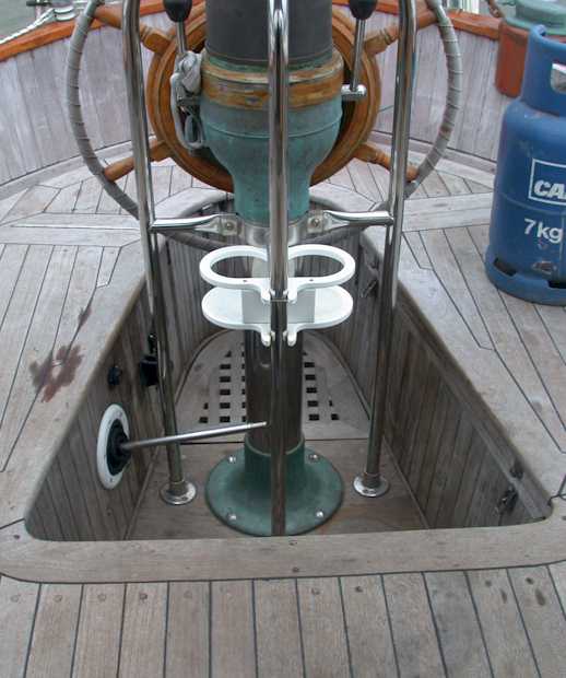
5.4. Steering system. Steering is by wheel mounted on a bronze pedestal bolted to the cockpit floor. Connection to the rudder is via pulley and 5mm wire rope to a quadrant attached to the rudder stock. Access for inspection and maintenance is via the cockpit locker. There is an emergency tiller which is fitted to the top of the rudder stock through a screwed bronze deck plate.
The Monitor wind-vane, when in use, is connected to the steering wheel by ropes leading to a clutch fixed to the wheel. Manufacturer’s instructions on use and maintenance are kept aboard the boat. A 12v automatic helm is fitted.
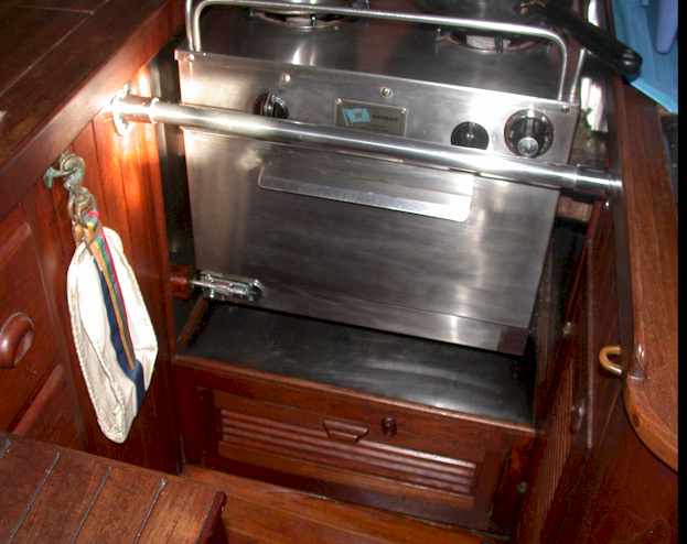
5.5. Gas system. A stern locker isolated from the rest of the vessel and vented to atmosphere from the bottom of the locker houses a propane/butane bottle and regulator. The sole gas outlet is to the galley cooker via an unbroken, unjointed length of crimped gas hose. The flow of gas is dependent on a 12v solenoid situated in the gas locker and controlled by a warning/detector panel in the galley. Gas is cut off if the 12v power supply fails, either by manual switching or automatically by detection of gas by the unit itself. A gas detector (valid for most combustible gases) is fitted at floor level in the galley area. If gas is detected the system automatically sounds a loud warning buzzer and shuts the gas system down by cutting power to the solenoid. The cooker has its own built-in flame failure system.
5.6. Fire protection.
The vessel is fitted with two 2.25kg dry chemical fire extinguishers, one in the forward compartment and one in the main saloon. The engine compartment is fitted with flame-retardant insulation. The galley compartment housing the gas cooker is lined on both sides, behind and underneath with stainless steel sheet.
5.7. Navigation lights. The vessel is fitted with red and green bow lights, mast running light and stern white light. There is a masthead tricolour.
5.8. Discharge prevention. A 15-gallon holding tank is fitted forward under the starboard settee in the saloon. Discharge of the toilet is direct to the holding tank. It is not possible to discharge the toilet directly to the sea. The holding tank can be emptied via a Y-valve either by hand-pump (fitted inside the washbasin cabinet) or by shoreside pump via the starboard deck fitting. The holding tank is vented to the starboard cabin side
|